IRLZ44N
Infineon (formerly International Rectifier) · MOSFETs · TO-220AB · Through-hole
Profile irlz44n Profiled: 31 Oct 2026
Lifecycle: Active
Availability risk: Low
Specification
Transcribed from the manufacturer datasheet
| Type | N-channel enhancement MOSFET, logic level |
|---|---|
| Vds | 55 V |
| Id | 47 A continuous at 25 °C, 33 A at 100 °C |
| Rds(on) | 22 mΩ at Vgs = 5 V, 25 mΩ at Vgs = 4 V |
| Vgs(th) | 1.0 V to 2.0 V |
| Gate charge | 48 nC total at Vgs = 5 V |
| Power | 110 W at 25 °C case, 3.8 W at 25 °C free air |
| Tolerance | Rds(on) ±10 % typical lot spread |
| Voltage rating | 55 V Vds, ±16 V Vgs |
| Lifecycle | Active |
| Datasheet reference | Infineon IRLZ44N datasheet, rev. 2023-08, figs. 1-4 and the SOA chart, plus the TO-220 thermal resistance table |
|---|---|
| Manufacturer | Infineon (formerly International Rectifier) |
| Mounting | Through-hole |
Substitute graph
3 Alternates
Interchangeable part numbers for this profile. A solid node is already profiled in this catalogue; a hollow node is a valid substitute that has no profile yet.
-
IRFZ44N not yet profiled
The standard-threshold sibling. Same 55 V 47 A die but Rds(on) is specified at 10 V, and at 5 V it is about 45 mΩ — double. It is half the price and is the single most common wrong substitution in this category: it works on a breadboard at 5 V and overheats in production.
-
IRLB8721PBF not yet profiled
Infineon 30 V 100 A logic-level TO-220, 4.5 mΩ at 4.5 V. Much better conduction, but only 30 V, so it is a 12 V and 24 V part, not a 48 V one. Check the current path before substituting upward.
-
STP55NF06L not yet profiled
ST 60 V 55 A logic-level MOSFET with 18 mΩ at 5 V. Slightly better performance and a higher voltage rating; the pinout is the standard TO-220 G-D-S arrangement so it substitutes mechanically without any change.
Selection notes
The only prose on this page
Why the L matters and where it stops
The L suffix means the die is processed for a low threshold and characterised at 5 V and 4 V gate drive. It solves 5 V microcontroller drive completely at low switching frequency. Above about 20 kHz the 48 nC gate charge becomes the problem: 5 V drive through a typical 100 Ω GPIO impedance gives a 4.8 µs transition, and at 20 kHz that is a tenth of the period spent in the linear region. Use a gate driver above 20 kHz.
110 W is a case-temperature rating
110 W is specified at 25 °C case, which requires an infinite heatsink. Free air, the same part is rated 3.8 W. The real design number is the junction-to-case thermal resistance of 1.5 °C/W plus your heatsink; at 22 mΩ and 10 A the conduction loss is 2.2 W, which needs roughly a 5 °C/W heatsink to stay under a 100 °C junction in a 40 °C ambient.
Gate drive and the body diode
The ±16 V gate rating means a 12 V drive is fine and 20 V is not. In a half-bridge, the slow body diode recovery of this generation of MOSFET matters: reverse recovery is around 100-200 ns, which produces shoot-through current if both devices are on for even a moment. Use a proper dead time of at least 300 ns, or select a MOSFET with a fast-recovery body diode.
Sources
Vishay Siliconix — https://www.vishay.com/docs/62253/sq9945cey.pdf · NIST — https://www.nist.gov/standardsgov/compliance-faqs-rohs
| Sourcing — Availability risk | TO-220 logic-level MOSFETs are made by Infineon, ST, onsemi, Toshiba, Vishay and several Chinese manufacturers, with pin-compatible parts widely available. The main risk is not availability but counterfeiting in the TO-220 power MOSFET market, which is significant; buy from franchised channels for anything that switches real current. |
|---|---|
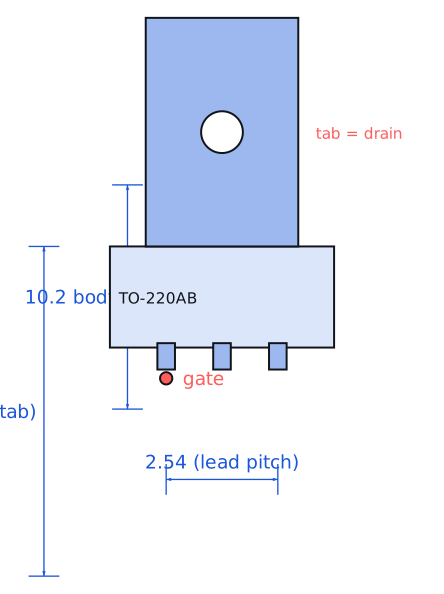
| Pinout and handling | Standard TO-220AB: pin 1 gate, pin 2 drain, pin 3 source, with the metal tab electrically connected to the drain. That tab connection is the trap: bolting two of these to a shared heatsink without an insulator shorts their drains together, which on a half-bridge is a direct short across the supply. |
Engineering information only. Verify every substitution against the manufacturer datasheet and your own operating conditions before committing a design. No pricing or vendor links appear on this page.