AO3400A
Alpha & Omega Semiconductor · MOSFETs · SOT-23 (3-lead) · SMD
Profile ao3400a Profiled: 15 Aug 2026
Lifecycle: Active
Availability risk: Medium
Specification
Transcribed from the manufacturer datasheet
| Type | N-channel enhancement MOSFET |
|---|---|
| Vds | 30 V |
| Id | 5.7 A continuous at 25 °C, 4.0 A at 70 °C |
| Rds(on) | 28 mΩ at Vgs = 10 V, 33 mΩ at Vgs = 4.5 V, 48 mΩ at Vgs = 2.5 V |
| Vgs(th) | 0.7 V to 1.4 V |
| Gate charge | 6.0 nC total at Vgs = 4.5 V |
| Power | 1.4 W at 25 °C with 1 in² copper |
| Tolerance | Rds(on) ±15 % lot spread |
| Voltage rating | 30 V Vds, ±12 V Vgs |
| Lifecycle | Active |
| Datasheet reference | AOS AO3400A datasheet, rev. 2023-02, figs. 1-4 (output characteristics, transfer, Rds(on) vs Vgs) and the safe operating area chart |
|---|---|
| Manufacturer | Alpha & Omega Semiconductor |
| Mounting | SMD |
Substitute graph
3 Alternates
Interchangeable part numbers for this profile. A solid node is already profiled in this catalogue; a hollow node is a valid substitute that has no profile yet.
-
SI2302CDS-T1-GE3 not yet profiled
Vishay 20 V 2.5 A N-channel in the same SOT-23. Lower voltage and about 2x the Rds(on) at 4.5 V; a direct footprint swap but a downgrade in current. Fine for LED and small-load switching, not for 3 A motor drive.
-
IRLML6344TRPBF not yet profiled
Infineon 30 V 5.0 A logic-level N-channel, 29 mΩ at 4.5 V. Very close electrically; the pinout is the same standard SOT-23 (gate on pin 1) so it drops in, but check the gate charge if you are driving it from a microcontroller at high frequency.
-
AO3400 not yet profiled
The non-A version. Same footprint, slightly higher Rds(on) and a lower 30 V rating shared with the A. It is a genuine substitute, and it is also the classic purchasing mistake: two part numbers that differ by one letter and by 20 % in performance.
Selection notes
The only prose on this page
Logic-level means 4.5 V, not 3.3 V
Rds(on) is specified at 10 V and 4.5 V, and the 2.5 V column is 48 mΩ — nearly double the 10 V figure. Driving this part from a 3.3 V microcontroller pin is common and works, but you are running at roughly the 2.5 V number, so a 2 A load dissipates 2² x 0.048 = 0.19 W in a SOT-23 with 90 °C/W of thermal resistance on a good pad. That is a 17 °C rise, which is acceptable — until you also count the gate drive losses at 20 kHz.
Gate charge sets the drive requirement
6 nC at 4.5 V means a 3.3 V GPIO driving at 20 kHz needs 6 nC x 20 kHz = 120 µA of average gate current. That is well inside a microcontroller's pin budget, so direct drive is fine at low frequency. At 200 kHz the current becomes 1.2 mA and the switching losses start to dominate the conduction losses; use a gate driver or drop the frequency.
Thermal limits more than current
The 5.7 A headline is at 25 °C case with a large copper pad. Real boards at 70 °C ambient support 4.0 A, and a minimal footprint cuts that further. A practical ceiling for continuous current in a SOT-23 is about 2 A unless you have measured the pad temperature; above that, move to a SOT-223 or a DPAK and stop fighting the package.
Sources
Vishay Siliconix — https://www.vishay.com/docs/62253/sq9945cey.pdf · Texas Instruments — https://www.ti.com/lit/an/slva840/slva840.pdf · NIST — https://www.nist.gov/standardsgov/compliance-faqs-rohs
| Sourcing — Availability risk | Alpha & Omega is a single-source for the exact part number, though there are many pin-compatible alternatives from Infineon, Vishay, onsemi and Diodes Inc. Recommend qualifying at least one alternate footprint-compatible MOSFET at design time; SOT-23 MOSFETs had 12-20 week lead times through 2021 and 2022. |
|---|---|
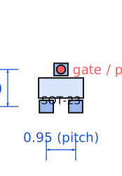
| Pinout and handling | Pin 1 gate, pin 2 source, pin 3 drain in the standard SOT-23 MOSFET pinout, with the single-lead side of the package usually being the gate for this family. The body diode is intrinsic and points from source to drain, which means an N-channel MOSFET will conduct in reverse unless the source is the more positive node. |
Engineering information only. Verify every substitution against the manufacturer datasheet and your own operating conditions before committing a design. No pricing or vendor links appear on this page.