SN74HC595N
Texas Instruments · Logic ICs · PDIP-16, 7.62 mm row pitch · Through-hole
Profile sn74hc595n Profiled: 12 Sep 2026
Lifecycle: Active
Availability risk: Low
Specification
Transcribed from the manufacturer datasheet
| Function | 8-bit serial-in parallel-out shift register with output latches |
|---|---|
| Supply range | 2.0 V to 6.0 V |
| Output current | ±6 mA per pin at 4.5 V, ±35 mA absolute max |
| Shift frequency | 25 MHz at 4.5 V supply |
| Input type | CMOS, Schmitt-trigger on shift clock |
| Propagation delay | 20 ns at 4.5 V |
| Tolerance | Output current bin ±20 %; logic thresholds guaranteed by datasheet limits |
| Voltage rating | 2.0 V to 6.0 V supply, 7 V absolute maximum |
| Lifecycle | Active |
| Datasheet reference | Texas Instruments SN74HC595 datasheet, doc SCLS041, rev. 2024-01, §8 timing requirements and the cascading schematic in §9.2 |
|---|---|
| Manufacturer | Texas Instruments |
| Mounting | Through-hole |
Substitute graph
3 Alternates
Interchangeable part numbers for this profile. A solid node is already profiled in this catalogue; a hollow node is a valid substitute that has no profile yet.
-
74HC595 not yet profiled
The generic part number carried by Nexperia, Diodes Inc and others. Functionally identical to the SN74HC595N; the only practical difference is that some second sources spec the shift frequency lower at 3.3 V, which matters only if you are clocking above 10 MHz.
-
SN74HC595DR not yet profiled
The SOIC-16 (SMD) version of the same die. Not a footprint substitute for a DIP socket, but the correct choice for a new design: it is half the price and takes a quarter of the board area.
-
TPIC6B595N not yet profiled
Power version with open-drain DMOS outputs rated 50 V and 150 mA per channel. Use it to drive relays, LEDs at higher current or 12 V strings directly; the logic side is the same. It cannot source current, only sink it.
Selection notes
The only prose on this page
Latches are the reason to use this part
The shift register and the output latch are separate. Data shifts in without appearing at the outputs until the latch clock (pin 12) rises. That is what lets you update a display or a relay bank without visible intermediate states — if you drive outputs directly from a shift register, the LEDs flicker through every intermediate pattern during the shift.
Current limits are per pin and per package
Each output handles ±6 mA comfortably and 35 mA absolute maximum, but the package has a total limit of about 70 mA across all outputs at once, and the ground pin has its own limit. Driving eight LEDs at 15 mA each is 120 mA total, which exceeds the package rating. Either multiplex at higher current, or use the TPIC6B595 power version, or add a ULN2803 on the outputs.
Cascading and the shift order
QH' (pin 9) is the serial output, and it is the last bit of the register, not a buffered copy of the input. Chaining N chips gives you N x 8 bits with the first chip holding the most recently shifted bytes. If your patterns come out reversed, it is almost always the shift order, not the wiring.
Sources
Texas Instruments — https://www.ti.com/lit/an/slva840/slva840.pdf · AEC — https://aecouncil.com/Documents/AEC_Q100_Rev_H_Base_Document.pdf · NIST — https://www.nist.gov/standardsgov/compliance-faqs-rohs
| Sourcing — Availability risk | The HC595 is a multi-source commodity; TI, Nexperia, Diodes Inc., Toshiba and several others make compatible parts, in DIP, SOIC, TSSOP and QFN. DIP versions are shrinking in availability but remain stocked; the SOIC is the safer long-term choice. |
|---|---|
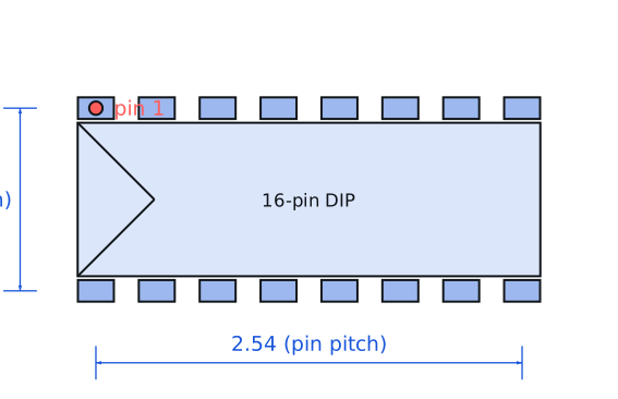
| Pinout and handling | PDIP-16 with pin 1 (QB) at the notch end. Pin 10 is the active-low master reset and must be tied high; pin 13 is the active-low output enable and must be tied low to see any output. Both are frequently left floating by mistake, which produces a chip that appears completely dead. |
Engineering information only. Verify every substitution against the manufacturer datasheet and your own operating conditions before committing a design. No pricing or vendor links appear on this page.