SS34
Multiple (Vishay, onsemi, Taiwan Semi, MDD) · Diodes · SMA (DO-214AC) · SMD
Profile ss34 Profiled: 18 Sep 2026
Lifecycle: Active
Availability risk: Low
Specification
Transcribed from the manufacturer datasheet
| Type | Schottky barrier rectifier |
|---|---|
| Average forward current | 3 A at 75 °C lead temperature |
| Reverse voltage | 40 V |
| Forward drop | 0.5 V typical at 3 A, 0.75 V max |
| Reverse recovery | No reverse recovery (majority carrier) |
| Reverse leakage | 0.5 mA at 40 V, 25 °C; rises to ~20 mA at 100 °C |
| Tolerance | Not applicable (rectifier grade) |
| Voltage rating | 40 V reverse |
| Lifecycle | Active |
| Datasheet reference | Vishay SS32-SS36 datasheet, doc 88741, rev. 2023-06, fig. 1 forward voltage vs current and the reverse leakage vs temperature curve on p. 3 |
|---|---|
| Manufacturer | Multiple (Vishay, onsemi, Taiwan Semi, MDD) |
| Mounting | SMD |
Substitute graph
3 Alternates
Interchangeable part numbers for this profile. A solid node is already profiled in this catalogue; a hollow node is a valid substitute that has no profile yet.
-
SK34 not yet profiled
Same 3 A 40 V class from a different die. Forward drop typically 0.05-0.1 V higher, which at 3 A is 0.15-0.3 W more heat — meaningful in a sealed enclosure, irrelevant in free air.
-
MBRS340T3G not yet profiled
onsemi 3 A 40 V Schottky in SMB rather than SMA. Bigger body, lower thermal resistance, better for continuous 3 A. Not footprint compatible.
-
SS34L not yet profiled
Low-leakage variant, roughly 10x less reverse leakage at temperature. Take it when the diode sits across a battery or a charged capacitor, where 20 mA of leakage at 100 °C is a real drain of 0.8 W.
Selection notes
The only prose on this page
Zero reverse recovery, but not zero loss
Because Schottky conduction is by majority carriers there is no stored charge to remove, so the switching loss is essentially only the junction capacitance. That is why an SS34 can run at 200 kHz where a 1N4007 cannot run at 20 kHz. The trade is a higher reverse leakage that increases about 10x per 60 °C, and a junction capacitance of roughly 200 pF that produces a spike every switching edge.
Leakage at temperature is the hidden cost
0.5 mA at 25 °C and 40 V is nothing. At 100 °C it is about 20 mA, which is 0.8 W dissipated in a part that is only rated for 3 A of forward conduction. In a boost converter running hot, this leakage can dominate the loss budget and, worse, it is a positive feedback loop: leakage heats the die, heat increases leakage.
Low-voltage designs only
A 40 V rating is a 24 V-rail part with derating, not a 36 V-rail part. Schottky breakdown is abrupt and there is no avalanche capability worth relying on, so a 30 V transient on a 40 V part can destroy it. For 48 V systems, use a 60 V or 100 V Schottky, or accept the higher forward drop of an ultrafast silicon rectifier.
Sources
Vishay Semiconductors — https://www.vishay.com/docs/81857/1n4148.pdf · Texas Instruments — https://www.ti.com/lit/an/slva840/slva840.pdf · NIST — https://www.nist.gov/standardsgov/compliance-faqs-rohs
| Sourcing — Availability risk | SS34 is made by at least a dozen suppliers across several countries, and it is the default 3 A Schottky in every catalogue. Because there is no single-source risk, price competition is aggressive and quality varies most on the low end; buy a branded part if the diode is in a mains-adjacent or safety-relevant path. |
|---|---|
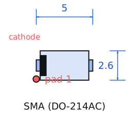
| Pinout and handling | Polarised: the cathode is marked by a band at one end of the SMA body. In a buck converter the cathode goes to the switch node and the anode to ground; reversing it puts the full input voltage across the output capacitor at the next switching cycle. |
Engineering information only. Verify every substitution against the manufacturer datasheet and your own operating conditions before committing a design. No pricing or vendor links appear on this page.