1N4007
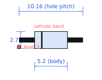
Multiple (Vishay, onsemi, Diodes Inc, Taiwan Semi) · Diodes · DO-41 axial, 2.7 x 5.2 mm body · Through-hole
Profile 1n4007 Profiled: 30 Sep 2026
Lifecycle: Active
Availability risk: Low
Specification
Transcribed from the manufacturer datasheet
| Type | General-purpose silicon rectifier |
|---|---|
| Average forward current | 1 A at 75 °C lead temperature |
| Reverse voltage | 1000 V repetitive, 1000 V non-repetitive |
| Forward drop | 1.0 V max at 1 A, 0.93 V typical |
| Reverse recovery | 2 µs typical, 30 µs max |
| Surge current | 30 A for one 8.3 ms half-sine |
| Tolerance | Not applicable (rectifier grade) |
| Voltage rating | 1000 V reverse |
| Lifecycle | Active |
| Datasheet reference | Vishay 1N4001-1N4007 datasheet, doc 88503, rev. 2022-09, fig. 2 forward characteristics and the surge rating note |
|---|---|
| Manufacturer | Multiple (Vishay, onsemi, Diodes Inc, Taiwan Semi) |
| Mounting | Through-hole |
Substitute graph
3 Alternates
Interchangeable part numbers for this profile. A solid node is already profiled in this catalogue; a hollow node is a valid substitute that has no profile yet.
-
1N4004 not yet profiled
Same 1 A die with a 400 V rating. Cheaper and, for a 120 V or 230 V mains rectifier, still adequate with margin if the input is clamped. Going down in voltage without a transient analysis is how rectifiers fail short across the mains.
-
1N4007G not yet profiled
Glass-passivated version. Same ratings, better moisture resistance. Worth the small premium in humid or potted assemblies; identical footprint so it is a true drop-in.
-
S1M not yet profiled
SMA surface-mount 1 A 1000 V rectifier. Same electrical class, no leads. Not a drop-in for a through-hole footprint, but the right answer for a new design: it removes two drill hits and solders better in a reflow line.
Selection notes
The only prose on this page
Do not use it as a fast diode
The reverse recovery time is 2 µs typical and 30 µs worst case. In a 50 Hz rectifier that is irrelevant. In a 50 kHz switching circuit the diode is still conducting backwards when the switch turns on, which produces a brief short across the supply and a spike that eventually kills the switch. Use a UF4007 (75 ns) or an S1M if you need a 1 A 1000 V part in a switching role.
The 30 A surge rating and inrush
One 8.3 ms half-sine at 30 A is the non-repetitive limit. A transformer with a 10 A inrush into a 470 µF reservoir puts a single 30-40 A pulse through the bridge, which is right at the edge. Add a 5-10 Ω NTC inrush limiter or move to a 3 A bridge, and remember the surge rating does not apply to repetitive pulses.
Thermal behaviour at 1 A
The 1 A rating is specified at 75 °C lead temperature, meaning the leads must be soldered into enough copper to sink about 1 W. On short leads with small pads the diode runs hot, and the 1.0 V forward drop means 1 W dissipated in a DO-41 package that has roughly 30 °C/W junction-to-ambient. Expect a 30 °C rise at 1 A; derate to 0.5 A on a tightly packed board.
Sources
Vishay Semiconductors — https://www.vishay.com/docs/81857/1n4148.pdf · NIST — https://www.nist.gov/standardsgov/compliance-faqs-rohs
| Sourcing — Availability risk | Mature commodity available from at least a dozen manufacturers, including low-cost Asian sources at $0.01-0.02 each in volume. Counterfeit and re-marked parts exist in this part number more than in most, so buy from franchised distribution if the application is mains-connected. |
|---|---|
| Pinout and handling | Polarised: the cathode is the banded end. In a bridge rectifier the four diodes are conventionally drawn with the band towards the positive output for two of them and towards the negative rail for the other two; getting one reversed produces a dead short across the transformer secondary on the next half cycle. |
Engineering information only. Verify every substitution against the manufacturer datasheet and your own operating conditions before committing a design. No pricing or vendor links appear on this page.