MFR-25FRF52-1K
Yageo · Resistors · Axial, 2.4 x 6.3 mm body · Through-hole
Profile mfr25frf52-1k Profiled: 23 Oct 2026
Lifecycle: Active
Availability risk: Low
Specification
Transcribed from the manufacturer datasheet
| Resistance | 1 kΩ |
|---|---|
| Rated power | 0.25 W at 70 °C |
| Element | Metal film, trimmed helical |
| Temp. coefficient | ±100 ppm/°C |
| Working voltage | 250 V |
| Operating range | -55 °C to +155 °C |
| Tolerance | ±1 % |
| Voltage rating | 250 V |
| Lifecycle | Active |
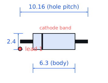
| Datasheet reference | Yageo MFR series datasheet, rev. 2022-10, §4 ratings and §6 colour code table |
|---|---|
| Manufacturer | Yageo |
| Mounting | Through-hole |
Substitute graph
3 Alternates
Interchangeable part numbers for this profile. A solid node is already profiled in this catalogue; a hollow node is a valid substitute that has no profile yet.
-
CFR-25JB-52-1K not yet profiled
Yageo carbon film, roughly one third the price. TCR is ±350 ppm/°C and noise is markedly higher, so it is fine for an LED ballast and a poor choice anywhere in a signal path.
-
RN55D1001FB14 not yet profiled
Vishay precision metal film in the same body size, ±1 % and ±25 ppm/°C with a 250 V rating. The reference-grade choice for a through-hole build; about 4-6x the cost.
-
MF0207FTE52-1K not yet profiled
Yageo 0207-size 0.6 W metal film, a physically larger cousin. Take it when you need more dissipation or a longer creepage path in the same 1 kΩ value.
Selection notes
The only prose on this page
Why metal film survives in a SMD world
Through-hole metal film still wins in three places: anywhere the board is hand-assembled or reworked repeatedly, anywhere a 250 V working voltage is needed on a cheap part, and anywhere the lead itself is a mechanical element. A 1 kΩ 0.25 W metal film also has better pulse tolerance than an equivalent 1206 chip because the heat has a ceramic core to spread into.
Reading the colour code correctly
Five-band 1 % parts are the most misread format in electronics. The tolerance band is separated by a wider gap and is usually brown, red, green, blue or violet — never gold or silver. If you see gold or silver as the last band it is a four-band 5 % part and the third band is the multiplier, not a digit. Sort by the gap, not by the colour.
Voltage rating and standoff
250 V working on a 2.4 mm diameter body is respectable, but the limiting factor in a mains-referenced design is the pad-to-pad spacing on the board, not the resistor. At 250 V you need about 2.5 mm creepage in air; that means a lead pitch of at least 10 mm and a slot or a routed gap if the board is conformally coated.
Sources
Universidad Nacional de La Plata — https://sedici.unlp.edu.ar/bitstream/handle/10915/162470/Documento_completo.%201a.%20Ed.%20-%20Barbero,%20Issouribehere%20y%20Leibovich.pdf-PDFA.pdf?sequence=1 · Vishay — https://www.vishay.com/docs/20035/dcrcwe3.pdf · NIST — https://www.nist.gov/standardsgov/compliance-faqs-rohs
| Sourcing — Availability risk | Axial metal film is a mature commodity, and 1 kΩ is the single most common value in the category. Lead time is effectively zero from catalogue stock at any distributor; the main supply risk is end-of-life consolidation as through-hole lines shrink. |
|---|---|
| Pinout and handling | Two axial leads, non-polarised. Colour code for 1 kΩ 1 % is brown-black-black-brown-brown (5-band); the fifth band is the tolerance band and reads brown for 1 %. Leads are 0.55 mm and take a minimum bend radius of about 1.5 mm measured from the body. |
Engineering information only. Verify every substitution against the manufacturer datasheet and your own operating conditions before committing a design. No pricing or vendor links appear on this page.