LVR03R0500FE12
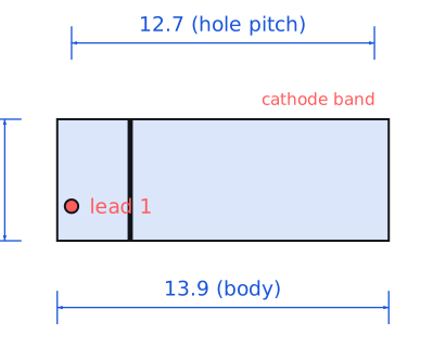
Vishay Dale · Resistors · Axial ceramic, 5.1 x 13.9 mm body · Through-hole
Profile lvr03r0500fe12 Profiled: 09 Oct 2026
Lifecycle: Active
Availability risk: Medium
Specification
Transcribed from the manufacturer datasheet
| Resistance | 0.05 Ω |
|---|---|
| Rated power | 3 W at 25 °C, derate linearly to 0 at 275 °C |
| Element | Wirewound on ceramic core, flameproof coating |
| Temp. coefficient | ±100 ppm/°C |
| Inductance | 20-40 nH at 1 MHz (wirewound) |
| Operating range | -55 °C to +275 °C |
| Tolerance | ±1 % |
| Voltage rating | Working voltage limited by 3 W at 0.05 Ω, i.e. 0.39 V across the element; terminal-to-terminal isolation 1000 V |
| Lifecycle | Active |
| Datasheet reference | Vishay LVR series datasheet, doc 30222, rev. 2023-05, derating curve and hot-spot temperature note |
|---|---|
| Manufacturer | Vishay Dale |
| Mounting | Through-hole |
Substitute graph
3 Alternates
Interchangeable part numbers for this profile. A solid node is already profiled in this catalogue; a hollow node is a valid substitute that has no profile yet.
-
ALSR-3-0.05 not yet profiled
Ward Leonard / IRC equivalent wirewound, same 3 W rating. Mechanically similar but the coating is silicone rather than the flameproof cement, so lead forming under stress differs; check the bend radius spec.
-
PWR220-2S-R050F not yet profiled
Bourns TO-220 style 0.05 Ω. Much lower inductance and can be heatsinked, but the through-hole spacing and body outline are completely different — not a drop-in, it is a redesign.
-
WSL2512R0500FEA not yet profiled
Surface-mount 2512 0.05 Ω from Vishay's own power metal strip line. Far lower inductance and better pulse handling for its size, but the axial part survives 3 W in still air where the 2512 needs copper area to reach 1 W.
Selection notes
The only prose on this page
Hot-spot temperature, not average
A 3 W wirewound in free air runs its centre winding at roughly 200 °C above ambient at full rated power. The silicone or cement coating is rated for that, but anything within 10 mm — heat-shrink, ribbon cable insulation, electrolytic capacitors — is not. Mount the part 5 mm off the board and keep electrolytics at least 15 mm away, distance measured from the body, not the leads.
Inductance is real
A wirewound 0.05 Ω carries 20-40 nH. At 100 kHz that is 12-25 mΩ of reactance, comparable to the resistance itself, so the part reads high and frequency-dependent. If the shunt is in a switching supply's current loop, use a metal-strip or metal-foil part instead, or the loop compensation will chase a moving target.
Inrush and pulse energy
Wirewound elements have large thermal mass and tolerate single-pulse energy well: this part absorbs roughly 20-40 J for a 100 ms pulse before the winding is at risk. That makes it a reasonable inrush limiter as well as a sense element, but repeated pulses at that level fatigue the winding and eventually open it.
Sources
Vishay — https://www.vishay.com/docs/20035/dcrcwe3.pdf · NIST — https://www.nist.gov/standardsgov/compliance-faqs-rohs
| Sourcing — Availability risk | Wirewound axial power resistors have consolidated onto a small number of makers and lead times stretch to 12-20 weeks on non-stocked values. The 0.05 Ω 1 % value is not a stocked item at most distributors, so plan a design that can accept 5 % or a 2512 substitute before you commit to it. |
|---|---|
| Pinout and handling | Two axial leads, non-polarised. The lead diameter is 0.8 mm and the standard mounting pitch is 12.7 mm with the body standing 5-10 mm off the board. That standoff is not cosmetic: it is the convection path, and pushing the body flush against the PCB roughly doubles the temperature rise. |
Engineering information only. Verify every substitution against the manufacturer datasheet and your own operating conditions before committing a design. No pricing or vendor links appear on this page.