NE555P
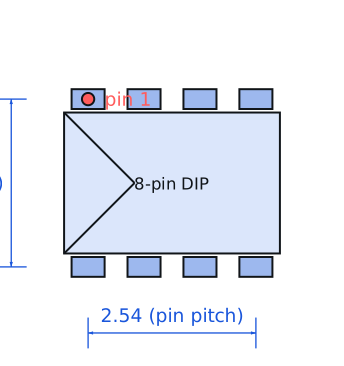
Texas Instruments · Logic ICs · PDIP-8, 7.62 mm row pitch · Through-hole
Profile ne555p Profiled: 28 Aug 2026
Lifecycle: Active
Availability risk: Low
Specification
Transcribed from the manufacturer datasheet
| Function | Precision timer, astable or monostable |
|---|---|
| Supply range | 4.5 V to 16 V |
| Output current | 200 mA source or sink |
| Timing accuracy | 1 % typical of calculated value with 1 % components |
| Supply current | 10 mA typical at 5 V, 3 mA at 15 V |
| Max frequency | ~500 kHz reliable, 2 MHz with care |
| Tolerance | Timing capacitor tolerance dominates; IC contributes ±1 % |
| Voltage rating | 4.5 V to 16 V supply, 18 V absolute maximum |
| Lifecycle | Active |
| Datasheet reference | Texas Instruments NE555 datasheet, doc SLFS022, rev. 2023-02, §7.4 (astable operation) and the timing formula table |
|---|---|
| Manufacturer | Texas Instruments |
| Mounting | Through-hole |
Substitute graph
3 Alternates
Interchangeable part numbers for this profile. A solid node is already profiled in this catalogue; a hollow node is a valid substitute that has no profile yet.
-
TLC555CP not yet profiled
CMOS version in the same DIP-8 pinout. Supply current drops from 10 mA to 0.4 mA, the output swings rail to rail, and the maximum frequency rises above 2 MHz. The trade is a weaker output drive at 100 mA and greater supply-noise sensitivity.
-
NE555N not yet profiled
The same die from ST or another second source. There is no meaningful difference in the timer itself; what differs is the output stage's crossover behaviour, which shows up as an extra 10-20 ns of jitter on the output edge.
-
ICM7555IPA not yet profiled
Another CMOS 555 with an even lower 60 µA supply current and a 2 V minimum supply. Use it for battery designs; the output stage is weaker still, so it drives a logic input well and a relay coil poorly.
Selection notes
The only prose on this page
The astable formula and its real accuracy
For an astable, f = 1.44 / ((R1 + 2 x R2) x C). With a 1 % metal film resistor and a 5 % X7R capacitor the timing varies about ±6 %, and the capacitor's temperature coefficient adds another 15 % over the full range. For anything that has to hold timing, use a C0G capacitor and a 1 % resistor, which brings the total spread to about ±2 %.
Why the classic 555 burns current
The bipolar output stage has a quiescent current of 10 mA at 5 V, and the internal reference divider draws a further 0.3-0.6 mA regardless of frequency. On a 9 V battery that is a 100 hour life before the load is even considered. For battery-operated timers, the CMOS variants are the only sensible choice; the NE555 is a bench and mains-powered part.
Decoupling and the output glitch
Every output transition draws a current spike of up to 200 mA from the supply, because the output stage is a totem pole switching a large current. Without a 100 nF ceramic within 5 mm of pins 1 and 8, that spike appears on the supply as a 100-300 mV glitch every cycle, which will couple into anything sharing the rail. A 10 µF bulk capacitor in parallel is also worth the space.
Sources
Texas Instruments — https://www.ti.com/lit/an/slva840/slva840.pdf · AEC — https://aecouncil.com/Documents/AEC_Q100_Rev_H_Base_Document.pdf · NIST — https://www.nist.gov/standardsgov/compliance-faqs-rohs
| Sourcing — Availability risk | The 555 is one of the most-produced ICs in history and is available from Texas Instruments, ST, onsemi and many Asian manufacturers. Counterfeits are common in the cheap DIP market and are usually functional but out of specification on supply current and maximum frequency. |
|---|---|
| Pinout and handling | PDIP-8 with pin 1 (ground) at the notch end on the left. Pin 4 is reset and must be tied high or the timer will not run — an unconnected reset pin floats and holds the output low, which is the single most common reason a freshly built 555 circuit does nothing. |
Engineering information only. Verify every substitution against the manufacturer datasheet and your own operating conditions before committing a design. No pricing or vendor links appear on this page.