CD4017BE
Texas Instruments · Logic ICs · PDIP-16, 7.62 mm row pitch · Through-hole
Profile cd4017be Profiled: 02 Oct 2026
Lifecycle: Active
Availability risk: Low
Specification
Transcribed from the manufacturer datasheet
| Function | Decade counter/divider with 10 decoded outputs |
|---|---|
| Supply range | 3 V to 18 V |
| Clock input | Schmitt trigger, DC to 5.5 MHz at 10 V |
| Output current | ±1.5 mA at 5 V, ±6.8 mA at 10 V |
| Reset | Asynchronous, active high (MR pin 15) |
| Propagation delay | 70 ns at 10 V |
| Tolerance | Output drive bin ±20 %; count sequence guaranteed by design |
| Voltage rating | 3 V to 18 V supply, 20 V absolute maximum |
| Lifecycle | Active |
| Datasheet reference | Texas Instruments CD4017B datasheet, doc SCHS029, rev. 2022-08, §9.2 functional diagram and the output timing waveforms |
|---|---|
| Manufacturer | Texas Instruments |
| Mounting | Through-hole |
Substitute graph
3 Alternates
Interchangeable part numbers for this profile. A solid node is already profiled in this catalogue; a hollow node is a valid substitute that has no profile yet.
-
CD4017BCN not yet profiled
The older National Semiconductor part number, now onsemi. Same function and pinout; the output drive at 5 V is specified slightly lower, which matters if you are driving LEDs directly from the outputs.
-
HEF4017BP not yet profiled
Nexperia version of the same counter. Equivalent behaviour, and it is the more commonly stocked DIP part in Europe. Note that its clock input is specified to a lower frequency at 5 V than the TI part.
-
CD4022BE not yet profiled
Octal version — 8 decoded outputs instead of 10, with the same pinout and the same counter core. Use it when you need 8 steps rather than 10, and remember that a circuit designed for 10 steps will simply skip two states.
Selection notes
The only prose on this page
Only one output is high at a time
The 4017 is a one-of-ten decoder: exactly one of Q0 to Q9 is high at any moment and the rest are low. That makes it a natural sequencer for a LED chaser or a stepper driver, and it is also the reason you cannot drive two loads simultaneously without extra logic. Q9 is special: it drives the carry output and resets the counter to zero on the next clock edge.
Decoding glitches on the outputs
The internal decoding is not fully synchronous, so during a clock transition the outputs can briefly show a narrow spurious pulse — typically 20-50 ns wide, appearing before the intended output goes high. For LEDs this is invisible. For anything that latches the output, add a 100 pF capacitor to ground on the clock line to slow the edge and blank the glitch.
Output drive at 5 V is weak
At a 5 V supply the outputs source only 1.5 mA, which is not enough for a modern LED at reasonable brightness, and the output high voltage droops to about 4.5 V at that current. At 10 V the same output handles 6.8 mA. If you want to run the counter at 5 V and drive LEDs, buffer each output with a transistor or use a 74HC4017, which has far better drive at low voltage.
Sources
Texas Instruments — https://www.ti.com/lit/an/slva840/slva840.pdf · AEC — https://aecouncil.com/Documents/AEC_Q100_Rev_H_Base_Document.pdf · NIST — https://www.nist.gov/standardsgov/compliance-faqs-rohs
| Sourcing — Availability risk | The CD4000 series is a long-lived commodity and the 4017 is one of its most popular members. DIP versions are still produced by TI, Nexperia and several Asian manufacturers, though the DIP package is slowly losing support across the industry. |
|---|---|
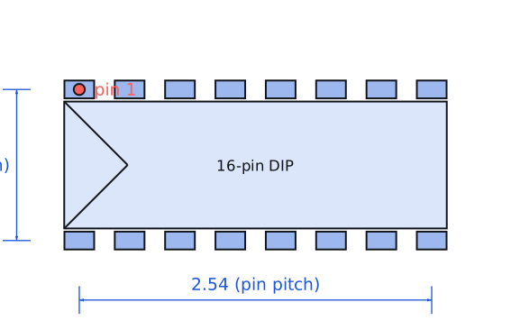
| Pinout and handling | PDIP-16. Pin 14 is the clock, pin 13 the clock inhibit (must be tied low to count), pin 15 the master reset (tie low), and pin 8 is ground with pin 16 the supply. The ten decoded outputs run from pin 3 (Q0) through pin 11 (Q9), and pin 12 is carry-out for cascading. |
Engineering information only. Verify every substitution against the manufacturer datasheet and your own operating conditions before committing a design. No pricing or vendor links appear on this page.