BAT54S
Multiple (Vishay, onsemi, Nexperia, Diodes Inc) · Diodes · SOT-23 (3-lead) · SMD
Profile bat54s Profiled: 14 Oct 2026
Lifecycle: Active
Availability risk: Low
Specification
Transcribed from the manufacturer datasheet
| Type | Dual Schottky, series-connected pair |
|---|---|
| Forward current | 200 mA per diode, 600 mA total |
| Reverse voltage | 30 V |
| Forward drop | 0.32 V typical at 1 mA, 0.8 V max at 100 mA |
| Reverse recovery | 5 ns typical |
| Junction capacitance | 10 pF typical at 0 V |
| Tolerance | Not applicable (Schottky grade) |
| Voltage rating | 30 V reverse |
| Lifecycle | Active |
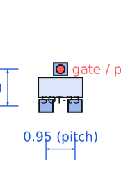
| Datasheet reference | Vishay BAT54 series datasheet, doc 85607, rev. 2024-01, pin configuration table and fig. 2 forward voltage curves for the S/A/C variants |
|---|---|
| Manufacturer | Multiple (Vishay, onsemi, Nexperia, Diodes Inc) |
| Mounting | SMD |
Substitute graph
3 Alternates
Interchangeable part numbers for this profile. A solid node is already profiled in this catalogue; a hollow node is a valid substitute that has no profile yet.
-
BAT54C not yet profiled
Common-cathode pair rather than series. Same die, different internal connection, and the two are not interchangeable — check the schematic symbol before substituting, because the package outline looks identical.
-
BAT54A not yet profiled
Common-anode pair. Again the same die with a third internal topology. Three parts, one footprint, three different circuits: this is the single most common substitution error in SOT-23 diode pairs.
-
PMEG3005AEA not yet profiled
Nexperia 30 V 500 mA Schottky in SOD-323 with a much lower 0.28 V drop at 10 mA. Single diode, lower drop, higher current. Use it to upgrade a clamp; not a drop-in for a dual.
Selection notes
The only prose on this page
The series pair and its classic job
BAT54S puts two Schottky diodes in series with the midpoint brought out, which makes it a compact way to build a clamp that references two rails or a wired-OR of two supply sources. Trivial example: two 3.3 V and 5 V rails feeding a load through the outer pins so the load runs from whichever is higher, with the midpoint left unconnected.
0.32 V at 1 mA is why Schottky wins here
At the small currents typical of a signal clamp — 1 mA or less — the Schottky drop is 0.32 V where a 1N4148 would be 0.6 V. In a 3.3 V logic design that 0.28 V difference is the gap between staying under a 3.6 V absolute maximum and exceeding it. The price is leakage: BAT54 reverse leakage at 30 V and 25 °C is 2 µA, and it grows about 10x per 55 °C.
200 mA per diode, not 600 mA
The 600 mA figure is a total package limit with both diodes conducting. In the series configuration only 200 mA can flow through the pair because they share a path, and the power dissipation of both junctions is inside a SOT-23 that has roughly 350 °C/W junction-to-ambient. At 200 mA and 0.5 V per junction, that is 0.2 W and a 70 °C rise — hotter than most people expect from a signal diode.
Sources
Vishay Semiconductors — https://www.vishay.com/docs/81857/1n4148.pdf · Texas Instruments — https://www.ti.com/lit/an/slva840/slva840.pdf · NIST — https://www.nist.gov/standardsgov/compliance-faqs-rohs
| Sourcing — Availability risk | The BAT54 family is a multi-source commodity made by at least six manufacturers. Note the suffix discipline: BAT54, BAT54A, BAT54C, BAT54S and BAT54SW are five different circuits in the same SOT-23 outline, and distributors list them on adjacent lines. |
|---|---|
| Pinout and handling | Polarised and topology-specific. In BAT54S the two diodes are in series: pin 1 is the anode of the first, pin 3 the cathode of the second, and pin 2 is the midpoint junction. Pin 1 is identified by the single lead on one side of the SOT-23 body when the two-lead side is on the right. |
Engineering information only. Verify every substitution against the manufacturer datasheet and your own operating conditions before committing a design. No pricing or vendor links appear on this page.