XT60PW-M
Amass · Connectors · XT60 board-mount male, right-angle, 2 positions · Through-hole
Profile xt60pw-m Profiled: 02 Nov 2026
Lifecycle: Active
Availability risk: Medium
Specification
Transcribed from the manufacturer datasheet
| Positions | 2 (power pair, keyed) |
|---|---|
| Current rating | 30 A continuous, 60 A peak |
| Voltage rating | 500 V DC |
| Contact resistance | 0.5 mΩ typical |
| Mating cycles | 1000 |
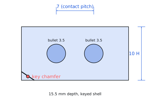
| Contact material | Gold-plated brass, 3.5 mm bullet |
| Tolerance | Contact resistance ±0.1 mΩ; insertion force 5-15 N |
| Voltage rating | 500 V DC, 30 A continuous |
| Lifecycle | Active |
| Datasheet reference | Amass XT60 series datasheet, rev. 2022-06, contact resistance vs mating cycles curve and the recommended through-hole land pattern |
|---|---|
| Manufacturer | Amass |
| Mounting | Through-hole |
Substitute graph
3 Alternates
Interchangeable part numbers for this profile. A solid node is already profiled in this catalogue; a hollow node is a valid substitute that has no profile yet.
-
XT60PW-F not yet profiled
The female board-mount right-angle half. Not a substitute — it is the mating half. Listed here because the -M and -F suffixes are easy to transpose on a purchase order and the two will not mate with each other.
-
XT30PW-M not yet profiled
Smaller 2.5 mm bullet version rated 15 A continuous. Same design language and keying, 60 % of the size. Use it below 15 A; using it at 30 A is a thermal failure waiting for a hot day.
-
AS150U-M not yet profiled
Amass anti-spark connector with a built-in pre-charge resistor, rated 70 A. The right choice above 40 V where the inrush into a large capacitor bank would otherwise pit the contacts on every connection.
Selection notes
The only prose on this page
Contact resistance is the rating, not the wire
At 0.5 mΩ per contact pair, 30 A dissipates 30² x 0.001 = 0.9 W in the connector, which is why the housing gets warm under load. A clone with 3 mΩ of contact resistance dissipates 2.7 W at the same current, three times the heat in the same volume, and the resulting temperature rise is what eventually melts the housing.
The inrush problem above 40 V
Plugging a 30 A connector into a pack with a large input capacitor bank produces a current spike limited only by the pack's internal resistance and the contact resistance. At 50 V into 1000 µF that is hundreds of amps for a few microseconds, and it pits the contact surfaces. After 20 connections the contact resistance has risen enough to feel hot. Use a pre-charge resistor or an anti-spark connector above 40 V.
Soldering the through-hole pins
The board-mount version has two large pins that need substantial copper to carry 30 A. Each pin should have at least 100 mm² of copper on at least one layer, and the pads should be connected to the power plane rather than to a thin trace. A 2 mm wide trace on 1 oz copper is about 1 mΩ per centimetre, which at 30 A is 0.9 W per centimetre of trace.
Sources
NIST — https://www.nist.gov/standardsgov/compliance-faqs-rohs · Texas Instruments — https://www.ti.com/lit/an/slva840/slva840.pdf
| Sourcing — Availability risk | Amass connectors are widely cloned, and the clones vary most in contact plating thickness and spring temper, both of which determine the 30 A rating. Genuine parts cost 3-5x the clones. On a 6S lithium pack at 30 A a clone will work and then, after a few dozen cycles, develop a hot spot. |
|---|---|
| Pinout and handling | Two 3.5 mm bullet contacts in a keyed housing that prevents reverse mating. The male board-mount version has the bullets recessed inside a shroud; the female has exposed sockets. Both polarities are visually distinguished by the housing chamfer, but on a board-mount part the silkscreen must still mark positive, because the housing itself does not. |
Engineering information only. Verify every substitution against the manufacturer datasheet and your own operating conditions before committing a design. No pricing or vendor links appear on this page.