USB4085-GF-A
GCT (Global Connector Technology) · Connectors · USB Type-C receptacle, 16 contacts, SMD with through-hole shell tabs · Hybrid SMD / through-hole
Profile usb4085-gf-a Profiled: 02 Sep 2026
Lifecycle: Active
Availability risk: Low
Specification
Transcribed from the manufacturer datasheet
| Position | 16 contacts (USB 2.0 only, no SuperSpeed pairs) |
|---|---|
| Current rating | 5 A per contact group, 3 A tested continuous |
| Voltage rating | 20 V DC |
| Mating cycles | 10000 |
| Contact resistance | 30 mΩ max initial |
| Shell | Stainless steel, 4 through-hole retention tabs |
| Tolerance | Contact position ±0.05 mm; insertion force 5-20 N |
| Voltage rating | 20 V DC, 5 A per group |
| Lifecycle | Active |
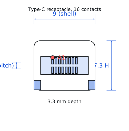
| Datasheet reference | GCT USB4085 drawing, rev. 2023-09, recommended PCB layout on sheet 2 and the reflow profile on sheet 4 |
|---|---|
| Manufacturer | GCT (Global Connector Technology) |
| Mounting | Hybrid SMD / through-hole |
Substitute graph
3 Alternates
Interchangeable part numbers for this profile. A solid node is already profiled in this catalogue; a hollow node is a valid substitute that has no profile yet.
-
USB4125-GF-A not yet profiled
Same 16-contact USB 2.0-only Type-C receptacle from GCT with a taller 3.3 mm profile. Choose it when the PCB is thicker or the enclosure gives more vertical clearance; the footprint is identical and the height is the only difference.
-
12401598E4#2A not yet profiled
Amphenol 16-contact Type-C receptacle with the same footprint family. Broader availability in some regions; check the shell tab positions, which differ by 0.1-0.2 mm between the two makers and will not fit a shared stencil.
-
USB4105-GF-A not yet profiled
The 6-contact power-only version with no data pins. Use it for a charging-only port; it is cheaper and simpler, but it cannot enumerate a device at all, so a user plugging in a phone will get power and no handshake.
Selection notes
The only prose on this page
16 contacts means USB 2.0 only, and that is usually enough
A 16-contact receptacle has the USB 2.0 data pair and the two CC pins but no TX/RX SuperSpeed pairs. For a 12 W charger, a serial port or a firmware update interface that is exactly what you need, and it costs about 40 % less than a 24-contact part. It will not support a USB 3.x device at anything above USB 2.0 speed, which is worth stating in your product documentation.
CC resistors you must not forget
A Type-C sink needs 5.1 kΩ from each CC pin to ground. Without them a Type-C source will not apply VBUS at all, because it detects a sink by measuring the CC line. This is the single most common fault in home-made USB-C boards: the connector is soldered correctly and nothing happens, because the two 0402 resistors are missing.
Mechanical soldering
The four shell tabs are the only mechanical attachment and they carry the full insertion force of up to 20 N. Hand soldering them with a fine tip leaves a weak joint that cracks after a few hundred cycles. Use a 2 mm chisel tip and plenty of solder, or put the tabs in the reflow profile, and keep a 0.5 mm gap between the shell and any other copper to avoid bridging.
Sources
Texas Instruments — https://www.ti.com/lit/an/slva840/slva840.pdf · NIST — https://www.nist.gov/standardsgov/compliance-faqs-rohs
| Sourcing — Availability risk | USB-C receptacles come from GCT, Amphenol, Molex, Wurth, TE and a large number of Asian suppliers. Because the mechanical dimensions are standardised but the shell tab placement is not, second-sourcing usually means a new stencil rather than a drop-in, so qualify one alternate before you need it. |
|---|---|
| Pinout and handling | 16 contacts in two rows plus 4 shell tabs. The four through-hole tabs carry the mechanical load and must be soldered on both sides of the board if the connector is on a board that gets plugged and unplugged. Note that a 16-contact USB-C receptacle has no SuperSpeed pairs: it presents the USB 2.0 D+/D- pins and the CC pins only. |
Engineering information only. Verify every substitution against the manufacturer datasheet and your own operating conditions before committing a design. No pricing or vendor links appear on this page.