B2B-PH-K-S(LF)(SN)
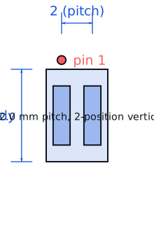
JST · Connectors · PH series 2.0 mm pitch, 2-position vertical header · Through-hole
Profile b2b-ph-k-s Profiled: 18 Aug 2026
Lifecycle: Active
Availability risk: Low
Specification
Transcribed from the manufacturer datasheet
| Pitch | 2.0 mm |
|---|---|
| Positions | 2 |
| Current rating | 2 A AC/DC per contact |
| Voltage rating | 100 V AC/DC |
| Contact resistance | 20 mΩ max |
| Mating cycles | 30 |
| Tolerance | Pitch ±0.05 mm; contact position ±0.1 mm |
| Voltage rating | 100 V AC/DC, 2 A per contact |
| Lifecycle | Active |
| Datasheet reference | JST PH series datasheet, rev. 2023-04, the 2.0 mm pitch reliability table and the crimp terminal extraction tool note |
|---|---|
| Manufacturer | JST |
| Mounting | Through-hole |
Substitute graph
3 Alternates
Interchangeable part numbers for this profile. A solid node is already profiled in this catalogue; a hollow node is a valid substitute that has no profile yet.
-
B2B-XH-A(LF)(SN) not yet profiled
XH series at 2.5 mm pitch with a 3 A rating and a locking ramp. Mechanically incompatible with PH housings — the XH is the locked, higher-current sibling and mixing PH and XH in one BOM is a common and confusing error.
-
53048-0210 not yet profiled
Molex PicoBlade 1.25 mm pitch equivalent. Much smaller for the same current class, but a completely different footprint and a different crimp terminal, so it is a redesign rather than a substitution.
-
B2P-SHF-1AA(LF)(SN) not yet profiled
JST SH series 1.0 mm pitch, 1 A rating. The right choice for a signal-only cable; do not use it for the power pair of a lithium cell, where its 1 A rating is a real fire risk.
Selection notes
The only prose on this page
2 A per contact is a thermal rating
The 2 A figure assumes a 22 AWG wire in the mating housing with both contacts loaded. With 28 AWG wire the same connector is limited to about 1 A, because the wire becomes the bottleneck. On a 2-position PH carrying 3.7 V from a lithium cell to a board, 2 A is 7.4 W of throughput and the connector will be warm but acceptable; 3 A in the same connector is outside the rating on every axis.
30 mating cycles is not an exaggeration
The 30-cycle rating is real. These connectors are designed to be plugged in during assembly and left alone. A product where the user disconnects the battery weekly will wear the plating through in under a year, and the failure mode is intermittent contact with rising resistance, which looks like a battery problem and is not.
Crimping, not soldering
The mating half of this connector is a crimp terminal, and soldering a wire into a crimp terminal instead of crimping it wicks solder into the contact spring and destroys its compliance. If you must solder wires directly to the board, solder to the header pins, not to a crimp terminal, and strain-relieve the joint with heat-shrink.
Sources
NIST — https://www.nist.gov/standardsgov/compliance-faqs-rohs · Texas Instruments — https://www.ti.com/lit/an/slva840/slva840.pdf
| Sourcing — Availability risk | JST PH is one of the most widely distributed connector families in electronics, but genuine JST parts and compatible clones are visually almost identical and the clones often use thinner plating. Buy genuine parts for anything that carries power, or verify the contact resistance of your source. |
|---|---|
| Pinout and handling | Two through-hole pins at 2.0 mm pitch with a friction-lock housing and a side-entry shroud. The connector is not keyed beyond the shroud shape, so a 2-position housing can be inserted upside down on some clones — check polarity markings on your own silkscreen rather than relying on the housing. |
Engineering information only. Verify every substitution against the manufacturer datasheet and your own operating conditions before committing a design. No pricing or vendor links appear on this page.