GRM188R71H104KA93D
Murata · Capacitors · 0603 · SMD
Profile grm188r71h104ka93d Profiled: 15 Sep 2026
Lifecycle: Active
Availability risk: Low
Specification
Transcribed from the manufacturer datasheet
| Capacitance | 100 nF (0.1 µF) |
|---|---|
| Voltage rating | 50 V DC |
| Dielectric | X7R, Class II |
| Tolerance | ±10 % |
| Temp. range | -55 °C to +125 °C, ±15 % over range |
| ESR / ESL | ~30 mΩ at 1 MHz, ~0.6 nH |
| Tolerance | ±10 % |
| Voltage rating | 50 V |
| Lifecycle | Active |
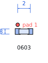
| Datasheet reference | Murata GRM series datasheet, rev. 2024-01, GRM188R71H104KA93D detail sheet plus the DC-bias and AC-voltage derating app note C02E |
|---|---|
| Manufacturer | Murata |
| Mounting | SMD |
Substitute graph
3 Alternates
Interchangeable part numbers for this profile. A solid node is already profiled in this catalogue; a hollow node is a valid substitute that has no profile yet.
-
CL10B104KB8NNNC not yet profiled
Samsung 0603 100 nF 50 V X7R. Electrically equivalent for decoupling; Samsung's DC-bias curve is slightly worse than Murata's above 25 V, so a 50 V part used at 30 V loses about 5-8 % more capacitance.
-
C0603C104K5RACAUTO not yet profiled
KEMET automotive version of the same value. Same body, AEC-Q200 paperwork and better lot traceability at roughly 1.8x the price.
-
GRM188R61H104KA93D not yet profiled
Same part on a 6.3 mm reel width rather than 8 mm. This is a packaging difference only — do not substitute it expecting an electrical change, but it is a real trap when a feeder is set for 4 mm pitch tape.
Selection notes
The only prose on this page
What 100 nF actually buys you
The classic self-resonant frequency of a 0603 100 nF is around 15-25 MHz with roughly 0.6 nH of ESL. Above that it becomes inductive, so a single 100 nF cap is not a broadband decoupler. For a 100 MHz digital rail the useful stack is 100 nF plus a 1 nF or 10 nF in the same package size, placed within about 2 mm of the pin.
DC bias derating
X7R capacitance falls with applied DC voltage. At rated 50 V this specific part retains roughly 55-65 % of its nominal capacitance; at 5 V it retains better than 90 %. The common mistake is choosing 50 V parts and then assuming full 100 nF at a 3.3 V rail — the real value there is closer to 92 nF, which is fine, but at 24 V the effective value drops to about 70 nF and a filter designed around 100 nF will be 1.4x off in frequency.
Piezo cracking and placement
Class II ceramics are piezoelectric: a board flex of 100 µm across the part can crack the electrode stack and create a short that only appears after thermal cycling. Keep MLCCs at least 5 mm from a break-away rail or a mounting screw, and orient them so the electrode planes are parallel to the expected bend line.
Sources
Murata — https://www.murata.com/en-global/support/faqs/capacitor/ceramiccapacitor/char/0005 · Siemens Matsushita Components — https://docs.rs-online.com/9018/0900766b80090f7a.pdf · Texas Instruments — https://www.ti.com/lit/an/slva840/slva840.pdf
| Sourcing — Availability risk | 100 nF 0603 is the highest-volume MLCC value in existence by a wide margin. During the 2018 allocation crunch it was the first value to go on strict allocation, so treat availability as a system risk rather than a part risk: qualify one alternate dielectric and one alternate manufacturer at design time. |
|---|---|
| Pinout and handling | Two-terminal, non-polarised. MLCCs have no polarity and no visible capacitance marking on 0603 — the body is blank. Once the reel is off the machine the part is effectively unidentifiable, so keep 100 nF and 1 µF 0603 reels physically separated on the line. |
Engineering information only. Verify every substitution against the manufacturer datasheet and your own operating conditions before committing a design. No pricing or vendor links appear on this page.