EEU-FM1V102
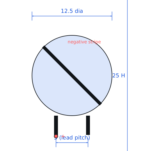
Panasonic · Capacitors · Radial, 12.5 x 25 mm, 5 mm lead pitch · Through-hole
Profile eeu-fm1v102 Profiled: 25 Oct 2026
Lifecycle: Active
Availability risk: Low
Specification
Transcribed from the manufacturer datasheet
| Capacitance | 1000 µF |
|---|---|
| Voltage rating | 35 V DC |
| Series | FM, low impedance, 5000 h at 105 °C |
| Ripple current | 2.09 A RMS at 100 kHz, 105 °C |
| Impedance | 0.024 Ω at 100 kHz, 20 °C |
| Leakage | ≤ 0.01 CV or 3 µA, whichever is greater |
| Tolerance | ±20 % |
| Voltage rating | 35 V |
| Lifecycle | Active |
| Datasheet reference | Panasonic FM series datasheet, rev. 2023-07, frequency correction table and endurance formula |
|---|---|
| Manufacturer | Panasonic |
| Mounting | Through-hole |
Substitute graph
3 Alternates
Interchangeable part numbers for this profile. A solid node is already profiled in this catalogue; a hollow node is a valid substitute that has no profile yet.
-
UPW1V102MHD not yet profiled
Nichicon PW, 1000 µF 35 V. Ripple rating 1.55 A rather than 2.09 A, so it substitutes only if the design has about 25 % ripple headroom. Impedance is comparable at low frequency.
-
EEU-FS1V102 not yet profiled
Panasonic FS, same can, 0.019 Ω impedance and 10000 h at 105 °C. About 40 % more expensive and the better choice when the capacitor sits in a hot switching supply that must run for years.
-
35ZLH1000MEFC12.5X20 not yet profiled
Rubycon ZLH, slightly shorter can (20 mm vs 25 mm). Different lead pitch in some variants — verify the 5 mm pitch version before laying out the footprint.
Selection notes
The only prose on this page
Why low impedance matters in a buck converter
The output capacitor's impedance at the switching frequency sets the output ripple for a given inductor current ripple. At 100 kHz this part is 24 mΩ, so a 1 A peak-to-peak inductor ripple produces about 24 mV of output ripple before the ceramic bank. A general-purpose 1000 µF 35 V part with 0.15 Ω impedance would produce 150 mV — the difference between a working supply and one that trips a downstream undervoltage detector.
Ripple current and heating
2.09 A RMS at 100 kHz and 105 °C is a substantial rating, and it is limited by internal heating, not by the electrolyte's breakdown. Each ampere of ripple through 24 mΩ dissipates 24 mW, so the full 2.09 A adds roughly 105 mW inside a can with about 15 cm² of surface area — a 20-30 °C rise. Split the ripple across two capacitors if you need margin; paralleling two also halves the ESR.
Mounting and lifetime
Lead pitch is 5 mm and the can is 12.5 mm diameter; do not place it within 3 mm of a heatsink or a power resistor. Life is 5000 h at 105 °C and doubles for every 10 °C below that (per Nippon Chemi-Con), so a capacitor held at 65 °C reaches 80,000 hours. In an enclosed case with no airflow, the ambient is often 20 °C above room temperature and this calculation ends badly — measure, do not assume.
Sources
Nippon Chemi-Con — https://www.chemi-con.co.jp/en/faq/detail.php?id=alLifetime · NIST — https://www.nist.gov/standardsgov/compliance-faqs-rohs
| Sourcing — Availability risk | High-capacitance low-impedance radials are a competitive segment with at least four credible suppliers. The practical constraint is board space, not availability: a 12.5 x 25 mm can does not shrink, so second-sourcing usually means finding a part with the same can, not a smaller one. |
|---|---|
| Pinout and handling | Polarised, long lead positive, stripe on the negative side. A 1000 µF can charged to 35 V holds about 0.6 J and will deliver a visible spark across a short; discharge it through a 1 kΩ resistor before handling a board that has been powered. Snap-in and radial variants of similar values have different lead spacing and are not interchangeable. |
Engineering information only. Verify every substitution against the manufacturer datasheet and your own operating conditions before committing a design. No pricing or vendor links appear on this page.